So I have a final-ish design for the pedals and have ordered some metal for the job. I know nothing about buying bits of metal, but I discovered that it is possible to order it from the internet. I found several suppliers on ebay and made some enquires. The metal arrived today in a hefty cardboard tube wrapped with bundles of heavy duty parcel tape.
The peddle is split into two parts, the first I am calling the 'peddle box' and is the basic base structure. The second part is the what I am calling the 'peddle arm' and consists of the actual peddle itself mounted, the arm/lever it is mounted on.
The peddle box will be made of five basic pieces; two side pieces made from 1/4” thick aluminium flat, three support pieces which are again 1/4” aluminium but this time aluminium channel/'u' section.
The main reason for choosing aluminium was the availability of the metal and the fact that it should be easier to drill/cut through than using steel. I have not done any metal working before so I am not sure quite how easy drilling/cutting will be before now.
The picture shows the side view of the design. The front support piece acts as a stop for the pedal – the pedal arm will rest against this piece when it is the rest position. The main support piece is where the 'spring assembly' will go. The rear support piece will double as the mounting for the pulley axle.
 |
| Accelerator Pedal Box Plan Side View |
Now I have the actual metal in my hands, I am not sure if the 1/4” thick stuff is overkill as this is really sturdy stuff. Anyway, the main support piece differs slightly for the brake and accelerator. In that the main support for the brake will be mounted horizontally allowing space for the 'L' bracket – which transfers force from the pedal to the load-cell.
 |
| Brake Pedal Box Plan Side View |
The relative lengths of 'going-upy' bit of the L and the 'going-acrossy' bit of the L are important by the way. The load-cell I brought is rated at 30kg so I want the maximum force the load-cell gets to be approaching 30kg (~300N) but not over. If the across bit is set, then a really long up bit would mean not much force gets to the load-cell; a really short up bit would mean too much force gets to the load-cell.
To work out how much force I am likely to press the pedal with, I go to my gym and get on the 'seated leg press' machine. Using just my left foot I do a bit of exercise. I guesstimate that with a fairly firm but not excessive 'standing on the pedal' braking manoeuvre the force on the pedal is about 300N (lifting 30kg).
Because the pedal arm acts as a 'first class lever' the 300N applied at the pedal is translated to a greater force at the opposite end. The wire rope pulling the spring would therefore be exerting a force greater than 300N when I apply a force of 300N to the pedal. Anyway, I have a spreadsheet working all this out which helped me set the size of the 'L' bracket.
The pedal arm assembly is made from thinner aluminium pieces (I say 'aluminium' but this is actually an aluminium alloy, 6082 T6 I think – but it is not important). To start with the actual pedals (as in the bit in contact with the foot) will be very basic looking but functional pieces made from 50mm wide aluminium flat.
 |
| Oops |
I try today to start making the thing. I have purchased a new hacksaw and some HSS 24TPI blades special for the job. I am still a bit unsure how easy it will be to cut through 1/4" thick Al. Turns out not too bad. But... Getting a straight cut is a bit tricky. The photo shows my first and second attempts. Was too impatient on the first cut, saw it was going awry but kept hacking away anyway. Second cut took a fair bit longer but I was pleased at the improvement over the first. The crooked cut in the first piece is now an 'extra design feature'.
Here is a list of the metal I got. I actually ordered enough for three pedals on the basis that; if I want to make a clutch pedal later on, I can do so. And/or if I mess up somewhere making the first set of pedals (quite likely) I'll have some spare pieces in stock ready to use.
* (6x) Al Flat Bar 4"x 1/4" cut to length=200 mm
* (3x) Al Square Tube. 1" Sq x 10 SWG, cut to length=380 mm
* (1x) Al round tube, 10mm OD, 1mm thick, length=250 mm
* (1x) Al flat bar, 2" wide, 1/8" thick, length=250 mm
* (1x) Al Rectangle Tube. 1.1/2" x 1" x 10 SWG, (3.25mm) length = 250 mm
* (1x) Al Unequal Angle. 4"x 2" x 1/4" length=30 mm
* (3x) Al channel/'U' section. 2"(base) x 1.1/2"(sides) x 1/4", length= 200 mm
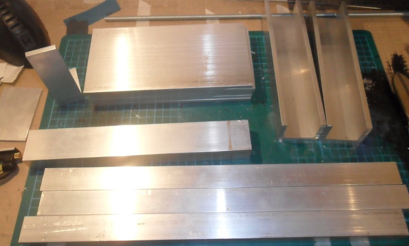 |
| Bits and pieces |
No comments:
Post a Comment