Current Project Status:
Pedals are made but need electronics parts making up -
Hall-effect sensor has been tested and works. Now fixed to pedal unit.
Load-cell is in place but needs an amplifier to work.
Amplifier circuit has been designed and parts are ready to go.
A preliminary design for a wooden wheel stand is sketched out. Wood has been purchased.
This post deals with my issues mounting the magnets to work with the hall-effect sensor.
So, I have decided on a method to mount the magnets and hall effect sensor to the pedal. The magnets will be mounted to the pedal arm and will be the moving bits. Whilst the hall effect sensor (HES) will be mounted to the side of the pedal unit and will be the stationary bit.
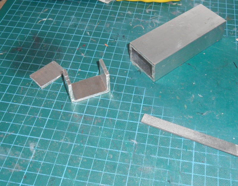
For the mounting of the HES and magnets I am using bits of left over aluminium. For the magnets I am using a piece of the 1.1/2 by 1" rectangle section - from the piece brought for part of the loadcell bracket. For the HES bracket a piece of 1" square tube - which was originally the 'spare pedal arm'.
I cut a piece of 1.1/2" x 1" 2 to 20mm 40mm in length. To make it into a channel section, I hacksaw the top side of the rectangle to make it into a U shape with the 1" sides forming the sides of the 'U'. I mount this on the back of the pedal arm, with a single 6mm bolt. The magnets will be positioned at either end of this piece - sticking out a bit to the side to be in line with the HES which will be mounted at the side of pedal unit sticking in. The height up the pedal arm at which this magnet bracket piece is mounted is quite important. Too high and the range of motion will mean that it will contact the HES and beyond when the pedal is pressed. Too low and the range of motion won't be sufficient to cause much change in the output of the HES.
 |
| This piece wasn't long enough and I had to cut another. (Poor me) |
I did some calculations to work out how high up the pedal arm I should mount the magnets – keeping in mind how far apart the magnets will be. I work out that it should be 97.8 mm (roughly) up from the centre of the axis.
To fit the magnets into the mounting bracket I just drill a 6mm hole and then bore this out until they fit. Go too far with one and have to hold it in with tape. One magnet is higher than the other because when the pedal arm swings there is some height offset due to the HES not being mounted on the same radius as the magnets. I did work out how much height offset there should be but won't detail that here (for any number of reasons). If you enjoy working that out then I think you would enjoy this project.
 |
| The incredibly simple hall-effect sensor circuit - can be wired in as a direct replacement for a potentiometer. I do this via the PCB terminal to make it a little easier to connect/disconnect things whilst testing. When using the pedals, magnets in bracket move towards camera as pedal is pressed. HES, of course, is stationary. |
 |
| Close up view of the magnet bracket. The black thing with three legs is the hall-effect sensor. I had to mark the magnets so I'd know which one goes where and which way round. |
Anyway, when it came to fitting the bracket I drilled a number of holes in the pedal arm so that it would be possible to mount the bracket at different heights later on if needed.
The HES is much more simple: it just needs to be in a fixed position, close to the first magnet when the pedal is at rest. To mount it, my plan is to make up the circuit on a piece of strip board. Mount this strip board to a piece of aluminium angle - here I will use rubber grommets to isolate the circuit from any metal. The actual HES itself will be protruding from the strip board, enough so that it is inline between the magnets. I can tweak the position and angle of the HES by gently twisting the pins on which it is mounted. The aluminium angle will be bolted to the side of the pedal unit. When it comes to mounting the HES bracket/aluminium angle, I drill a whole series of holes in the side to allow tweaking of the height of the HES. I find the HES is secure enough when the bracket is fastened with just one bolt.
 I decided to make the angle myself - from a piece of square tube. I take the 1" square tube and cut to length (105mm). Next I carefully hacksaw along the length just the thickness of the metal from the edge. Repeat on the “symmetrically opposite side” (I think) and bingo, two pieces of L. I have ended up using the second piece, and a few other offcuts, as brackets to fix the pedal units to wooden bases. To fix these brackets in place, it is a relatively simple job to drill holes in the side of the pedal units, holes in the brackets then bolt them together. To fix the rear of the pedal units, I have drilled two holes in the 'rear support' piece (which should fit flush to the bottom edge of the pedal unit) and bolted through these.
 |
| Pedal unit mounted to wood base. M4 Across, M5 Up |
No comments:
Post a Comment